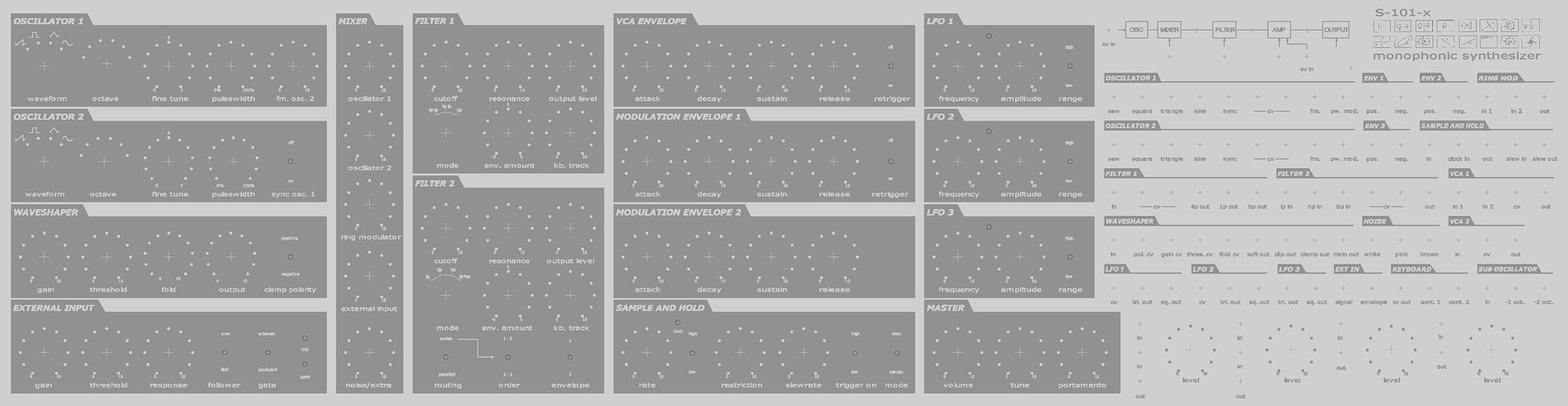
 The S-101-x Synthesizer
The S-101-x is a monophonic analogue synthesizer built by me over the course of some three-four years. I started planing to build a semimodular prepatched synthesizer sometime in the late summer of 2004 and it was more or less built, set up and properly tuned in January 2008.
This page is intended as some sort of documentation of the building process and to share my thoughs and experiences for those that are interested and to provide some inspiration to other people building synths.
Most of the circuits are other peoples designs, sometimes with a few additions and modifications by me. Most of them are built on purchased bare PCBs. Some of the circuits, like the Moog ladder filter are classic circuits that have been around for a long time.
And no, I don't take requests, though if you have questions or just want to say hi, I can be reached at gusand[a]etek.chalmers.se
And if you're wondering what kind of music I make, take a look here myspace.com/xorbsweden and here xorbmusic.tk
Gustav Andersson
Last updated 19 Feb. 2008.
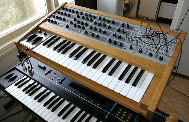
 |
| The S-101-x on top of an ESQ-1. |
Specifications:
2 VCOs (saw, pulse, triangle, sine), sub oscillator 1 och 2 octaves down.
2 VCFs with 4pole lp, 1pole lp, bp and lp, bp, hp respectively.
Waveshaper/distortion
Ringmodulator
External input with envelope follower and gate extractor
Noise (white, pink, brown)
3 ADSR envelope generators
4 LFOs, 2 with voltage control
Sample and hold circuit
3 octave keyboard with pitch and modulation wheels
Patch bay
Sounds
No page like this would be complete without some soundclips of course.
1 - Some basic octave basses with the moog filter.
2 - Both filters in series, maximum resonance and messing with the pitch wheel.
3 - Triggered with guitar through the sub oscillator and the Steiner filter in bandbass mode. Tracking is surprisingly good within a limited range.
4 - Triggered with a TR-505 drummachine and different modulations such as env to pitch and ringmodulating the external input with an oscillator.
5 - It can do syncleads as well.
History
A numbers of years back members of SAS - svenska analogsympatisörer, a swedish mailing list for analogue synthesizers that I sort of lurked on at the time, decided to start their own modular synth project. So plans and schematics for a VCO and a PSU were made and groupbuys of components were organized. I signed up for a PSU and 2 VCOs, the plan was to build a small modular of some sort. I built my 2 oscillators and power supply into a rack case.
After that, not much happened really. They still haven't finished the VCA module, which was supposed to be the third module. And after a while I started thinking progress was a bit slow and that it might be better so build a smaller self contained semi modular synth rather than a huge modular system. I was thinking of something similar to the MS-20, I liked the idea of having a prepatched signal chain with a patchbay with normalized connections that you could break if you wanted. Basically the flexibility of a modular combined with the ease of use of a prepatched synth.
I also wanted something that could be finished and be playable in a reasonable amount of time, maybe a year or two. This was in the summer 2004 so it eventually took over 3 years, quite a bit more than I had expected but I get the feeling that that's quite common with these kinds of projects.
I started looking around for interesting modules and circuits to incorporate and I ended up buying a bunch of PCBs from Oakleysound and a Steiner Synthacon filter PCB from Ken Stone.
I also found the ASM-1 but since I already had built the oscillators and had PCBs for the filters I planned to design and etch my own boards for LFOs, envelopes and VCAs. I actually drew and etched a board with 4 ASM-1 LFOs on it and it remains the only PCB in the whole synth that's designed by me. The suboscillator, mixer, modwheel circuits etc are all built on perfboard. In the end I felt that making my own pcbs would simply take too much time so I ended up ordering an ASM-2 board from Elby Designs even though I was only going to use around half of the modules on the board.
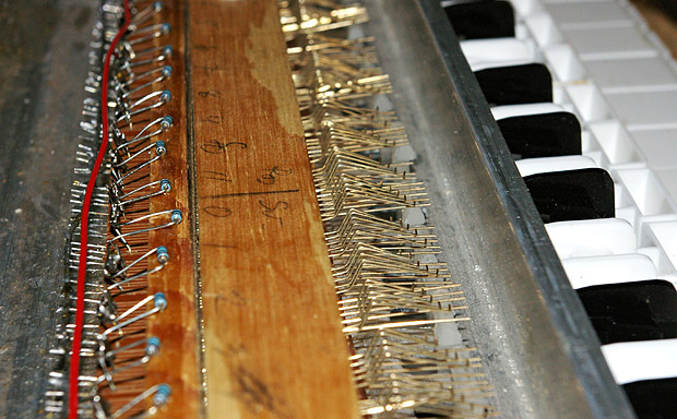
Keyboard
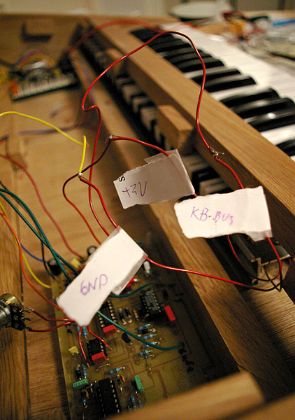 |
| The keyboard controller board installed. |
The keyboard controller is a circuit from Ray Wilson's Music from outer space. It works quite well but i had some problems at first with the sample and hold circuit which stopped after hade changed c13 6,8nF and c14 to 10nF. This also reduced the delay of the trig pulse from 11 ms to about 5 ms. It seems to give slightly different output voltages everytime you hit a key, this could be due to the switches bouncing or something similar, I haven't look into it in detail since the differences are quite small, they only correspond to a +/- 2-3 cents difference in frequency. Which is quite acceptable.
If I would have to rebuild it today though I would probably have gone with a midi keyboard, either a stripped commercial unit or a bare keyboard with electronics from Doepfer and a midi to CV converter. That would not only provide midi in and out but also add velocity as a modulation source and make it possible to have portamento that would be switched in only if you played two keys at once and similar things.
Oscillators
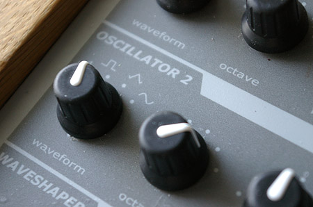
2 SAS VCOs. These are based on the ASM-1 VCO with added waveshapers to give triangle and sine waveforms. They also have sync and linear frequency modulation inputs. Basically everything you could ask for from a VCO. They are not identical to the ASM-2 VCOs, even though they have the same specifications the circuits themselves are different.
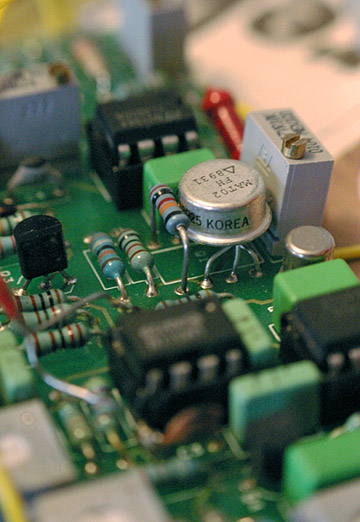 |
| MAT-02 transistor pair and tempco |
Picture shows the MAT-02 matched transistor pair and tempco. Ideally the temperature dependancy in these components should cancel each other out and should completely compensate for temperature differences. To keep them at the same temperature i covered the connection between them with heat conducting paste. The optimal solution would be something like Jörgen Bergfors's who made a special module with a MAT-02 and tempo moulded into araldite to keep any air moving around from .
My solution works pretty well though while not perfect. It's about 70-80 cent sharp over a 3 octave range when cold. Which works out to around 25 cents sharp per octave which is a little too much to be really playable. This drops rather quickly when turned on but it still takes about 15-20 minutes for it to settle in tune perfectly.
 |
| Oscillator section |
Filters
Filter 1 is an Oakley Superladder II, a Moog transistor ladder clone by Tony Allgood of Oakleysound. It also has a few extras such as a bandpass output and a one pole lowpass output. The 1 pole output is nowhere as fat and smooth as the 4 pole output but has more bite and high frequency fizz and is really quite usefull. It actually has voltage controlled resonance as well but there wasn't really room on the panel for more connections and i can live without it.
 |
| Superladder |
The second filter is a Steiner Synthacon clone. I got the PCB from Ken Stone. This filter is rather unusal since most (if not all) other voltage controlled filters used in synthesizers have one input and several outputs for different filter responses, lowpass, highpass and so on. This filter has only one output but has 3 inputs for lowpass, bandpass and highpass respectively. So the obvious questions is of course what happens when you feed different signal into the inputs at the same time? Well you basically get the low frequencies of the signal sent to the lowpass input and the high frequences from the highpass input, quite an interesting effect.
It also has an added bonus of going completely bonkers with the resonance cranked up. It distorts heavily and the selfoscillation seems to "lock" onto different harmonics in the signal in a rather chaotic and interesting way.
This is really a nice little filter that gives a good contrast to the smooth, expensive sounding Moog filter, not to mention cheap and easy to built, parts count and pcb size is probably less than one fifth of that of the superladder and has no expensive or difficult to find parts.
To save myself from a lot of patching i wired up two switches that enables me to use the filters either in parallell or in series, in which case the second switch sets the order of the two filters.
Wavehaper
The waveshaper is an Oakley wavefolder. More or less a distortion/clipper with the added ability to mix back the clipped part of the signal, sort of folding the waveform back on to itself.
External input
 Another Oakley module, this one is a preamp, envelope follower and a gate extractor with variable hysteresis. I had some thoughts about including some sort of "pitch to cv" circuitry, like in the MS-20 since I wanted to be able to run guitar through it. But in the end I decided against it since I wanted to get the whole project done in a reasonable amount of time and a clone of the MS-20 circuitry would require prototyping, testing, pcb layout, etc and quite a bit of work and i didn't really feel I had the time and energy to do it. And after trying a friends MS-20, I realized the tracking wasn't exactly stellar either so maybe it's not such a big loss.
Sample and hold
Yet another Oakley design. But really, the Oakley modules are great. Classic designs with a few cool extra features and nice professional circuit boards. This has two modes, track and sample in addition to a restriction control which controls how much the output is allowed to change from one sample to the next.
LFOs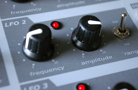
The synth has a total of 4 LFOs, 2 of which are voltage controlled. (I wonder if that's somewhat of a record for a monophonic synth). The 2 not voltage controlled, one of which is hardwired to the sample and hold clock input, are ASM-1 designs. The 2 Voltage Controlled are from the ASM-2 board. Both of them have square and triangle waveshapes. The ASM-2 circuits seems to be more stable at low frequencies and goes down to periods of over well 5 minutes at the lowest setting.
All LFOs have been modified with a switch for switching the range into audio frequencies where the maximum frequency is somewhere around 400 Hz except for the sample and hold LFO which goes over 20 kHz, making it possible to use the S&H as an analog bitchrusher. The ASM-1 design has also been given an LED to give a visual indication of the speed, and the more flashing lights the better.
Ringmodulator
Well it's a pretty standard ringmodulator, sum and difference frequencies you know.
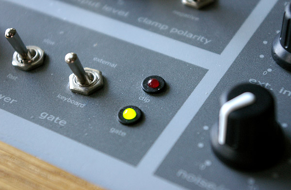
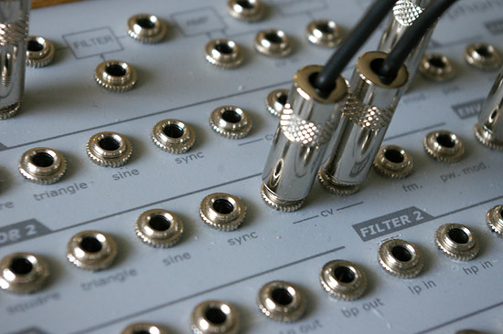
Patch panel
Even though I was building a semimodular synth I still wanted to keep as much as possible of the flexibility and the ability to patch anything to anything of a fully modular synth. So I opted for a patchbay similiar to that of Korgs MS-series but with basically every possible modulation input or output available.
 Most fully modular synthesizers have attenuators on the inputs of modules though some have them on the outputs. In trying to keep things compact yet flexible my solution isn't entirely consistent. Some common modulations such as oscillator sync and oscillator 1 to 2 frequency modulation have their own dedicated controls. The LFOs have a common output level control for both waveforms and the filters and waveshaper have volume controls.
However most signal and cv inputs or output have no level controls.
Most fully modular synthesizers have attenuators on the inputs of modules though some have them on the outputs. In trying to keep things compact yet flexible my solution isn't entirely consistent. Some common modulations such as oscillator sync and oscillator 1 to 2 frequency modulation have their own dedicated controls. The LFOs have a common output level control for both waveforms and the filters and waveshaper have volume controls.
However most signal and cv inputs or output have no level controls.
Instead I have 4 separate mixers/attenutator modules than can be patched in if you wish to controll the amount of modulation. This keep the number of panel components down and frees up panel space.
The choice of connectors was pretty easy. I don't like the look of banana plugs and 6.35 mm jacks are way to big to fit. Which leaves only 3.5 mm jacks. The sockets are Switchcraft and they have a small spring inside to keep the normalization tab from being bent out of shape so I'm fairly confident that they'll hold
I also made a set of custom made patch cables to go with it, including a few multiples for splitting signals.
Envelopes
The ASM-2 board has 2 envelope generators and originally I was only planning on having 2 but I had an unpopulated envelope/vca board from Oakleysound lying around and a third envelope might come in usefull, either you could use one for each filter or to control something else. And I would be getting another VCA as well. The oakley and ASM-2 envelope circuits are very similar, they both use some logic and switches to charge or discharge a capacitor through the panel mounted pots. The ASM-2 envelopes also has a trigger input to retrigger the envelope even if the gate is on.
I changed the capacitor in the Oakley circuit to 4.7µF to match the times of the ASM envelopes. Oakley recommends logarithmic pots while the ASM-2 schematic says linear. I tried both and would probably recommend log pots, the linear ones tend to be a bit touchy for short attack and decay times. Log makes it easier to finetune those but the difference is not huge. Linear also makes it easier to se what the current value is from the knob position.
I also added inverting outputs to all the envelopes to give both positive and negative modulation. I find it rather weird that the ASM-2 envelopes didn't have that, in particular since there is an unused half of a TL082 on the board that could easily be used to make an inverting output.
One other thing I noted which might be of interest to ASM-1 or 2 builders is that it's possible to turn the attack peak level trimmer down so low that it never switches over into the decay phase. So if your envelope seems stuck in the attack phase make sure that's not the problem. It happened to me and I didn't find any mention of it in the documentation.
The retrigger function is switchable but I didn't find it to be as usefull as I first thought it would be. Being used to digital envelopes I had expected the envelopes to start a new attack phase from zero when retriggered and I hadn't studied the schematics carefully enought to realize that was not what was going to happen. Instead they start from the current voltage stored in the capacitor which in case the envelope is running or has a long decay setting is far from zero volts. This is a consequence of the design and I guess the only way around it is to include some circuitry to completely drain the capacitor at the start of every attack phase.
VCAs
Three in total, one from the Oakley board which is a transistor design and two CA3080-based from the ASM-2 Board. One of the OTA-VCAs is hardwired to envelope 1 as the main output VCA. Another VCA is normalized to the modulation wheel and and one of the LFOS which in turn is normalized to the oscillators so you dont have to use up half the patch cables just to route the vibrato to the mod wheel.
Sub oscillator
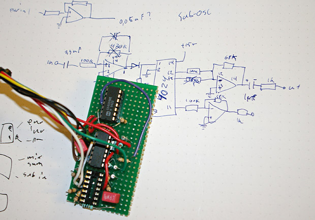 |
| Sub oscillator board, also includes the mixer and master output amplifier. |
Noise generator
Well you might need a bit of noise every now and then I guess. It's the noise generator from the ASM-2 board. Nothing special really. It has white noise filtered noise and low frequency random noise. I didnt mount the pots for the filtered noise to the panel but used trimpots instead since I didn't think I was going to use them much and the panel was rather crowded as it was anyway. I also added a little RC filter as a high pass filter to the white noise output since I was getting some 50Hz hum from it and that took care of it.
Pitch and modulation wheels
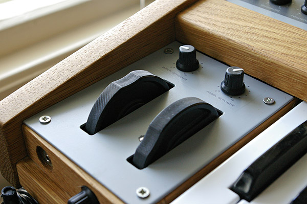 These are replacement parts from Doepfer. The original idea was to have a joystick but finding a suitable joystick that wasn't ridiculously expensive proved to be easier said than done. So instead I chose a more traditional approach. Which works really well though.
The pitch wheel is hardwired to the oscillators but can be used to modulate other things as well. The two knobs controlls the amount of modulation coming from the wheel. At maximum this is about +/- 5 volts which means you can sweep roughly the entire audible range with the pitch wheel if you like.
Casing
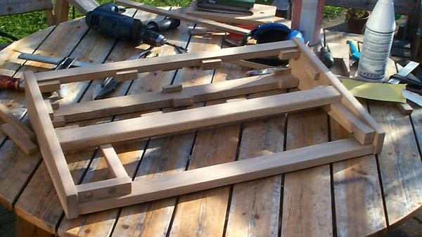 The casing is built from oak, glued together and then oiled which gives it a darker tone than in the pictures below. I didn't manage to get the frame completely straight with all the corners at 90 degrees when I glued it togethere so it's slightly askew. It's not really visible but I had to compensate for this when making the panels to make sure they fitted perfectly.
I guess the lesson learned is to be carefull when doing your woodwork.
As a totally unrelated note, this is a perfect example of how much better digital cameras have become in just a couple of years. These pictures were taken with a Kodak DC210 with something like half a megapixel and it took a lot of post processing just to make them look acceptable. My current cellphone camera probably takes better pictures than this. All of the more recent photos are taken with a Pentax *ist DS in case anyone wonders.
 |
| Recessed headphone output and volume control. I had to use a 3.5mm socket instead since the large 6.35mm socket would obstruct the pitch wheel |
At this time I had neither a complete control panel layout or even the final specifications ready which in hindsight was not a very good thing. Eventually there was barely room for all the circuit boards inside of it and fitting all the controls on to the front panel took quite a bit of work.
For whatever next big project I start on I will certainly finish the panel layout and make sure there's room for everything before I start working on the enclosure.
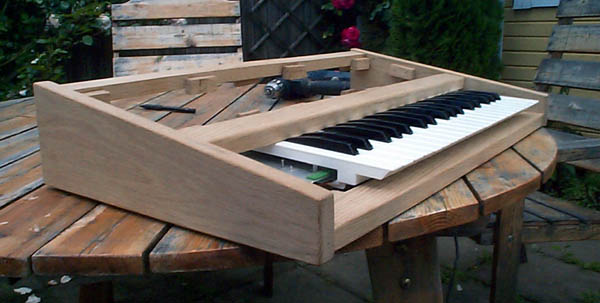 |
| Test fitting the keyboard. |
Panel layout
 The front, back and modwheel panels are 2 mm aluminium, a guy at the mechanical workshop at my university
helped me cutting them to the exact sizes.
The front, back and modwheel panels are 2 mm aluminium, a guy at the mechanical workshop at my university
helped me cutting them to the exact sizes.
The design of the front panel is rather "inspired" by the Access Virus line of synths. Not a complete rip off though I hope. To the right and below are some photoshop composites I made with some early panel designs. The design it self was made in Frontdesigner. The program does have it's quirks but it has great functions for making nice scales around knobs and sliders and other things.
 Techniques for making front panel graphics is a rather complex subject in itself. And for this project I wanted something that didn't have that homebuilt look but something that would look professional and at least from a distance could be mistaken for a commercial product.
Steve Thomas has a great page on the subject where he has tested several methods. There are even those who have experimented with silkscreening panels themselves for that really professional look.
I did also consider engraving the whole panel though the design I settled on wasn't really suitable for engraving. Engraved panels can look really good though and seems to be quite popular with the synth DIY-crowd.
Eventually I decided on using Lazertran paper. Not the laser version Steve Thomas recommends but the inkjet version. The inkjet version is different in that it dries opaque rather than clear and cannot be baked on in an oven like the laserjet version can. However a coat of varnish will make the decal transparent again and is more or less needed to protect the surface from scratches.
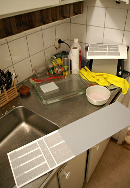 |
| Applying the lasertran decal |
The paper is basically a waterslide decal that you print your front panel design on and after it's dry you soak in water for 30 seconds and then you can carefully slide the decal onto the panel. It's rather tricky to work with and you have to be really carefull about not trapping air bubbles underneath as they will be visible once you've clearcoated the panel.
In their instructions they recommend a small amount of denatured alcohol on the panel as this makes the decal softer and should adhere better. Not too much though as this makes the decal melt and crumble. I found that a 50-50 mix of denatured alcohol and water poured on to the panel before applying the panel helped the decal stick properly.
The surface must also be as flat and smooth as possible since the smallest speck of dust or scrath will be visible through the decal. My panel had some scraches that I thought were close to invisible when painted but after the clearcoat was applied you could easily see that a line of bubbles had formed along it.
I also found out the hard way that not all spray varnishes will make the lasertran transparent again after it has dried. The CRC propaint that I got from Clas Ohlson worked for me. However than one gives a shiny finish but a final coat of a matte varnish took care of that.
But despite these issues the results are quite impressive and apart from where the edges of the decal overlap you might easily think the graphics are printed directly onto the panel.
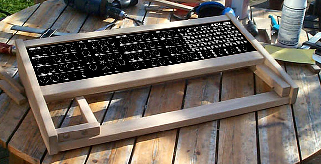
The final panel layout can be seen below (clickable image)
The "logo" in the right corner is "borrowed" from Three Distributions from the Aspen multimedia magazine.
More pictures from the building process
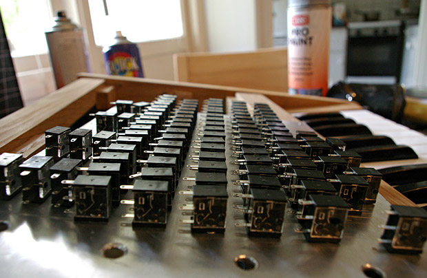
 Underside of keyboard, there's actually 5 switches for each key but i decided to wire them all in parallell since I only needed one switch per key.
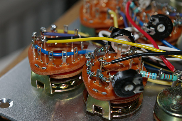
 Washers to keep the pot shafts down a bit so the knobs are flush against the panel.
 All the sockets in place.
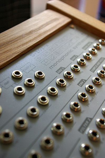 Close up of panel. Remember to check things thourougly before printing, otherwise you'll end up with 3 "ENV 1" on the panel. Embarrasing mistake but at least I spelled synthesizer correctly.
 If you dont have the right resistor values at hand you can always improvise by connecting 2 in series or parallell.
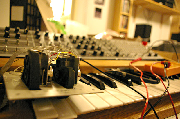
 Testing.
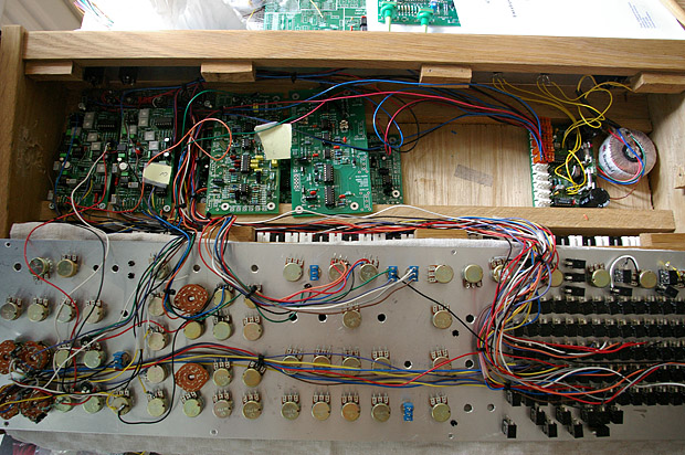
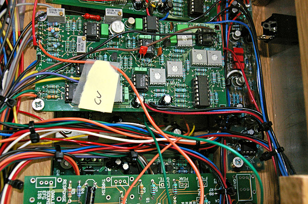
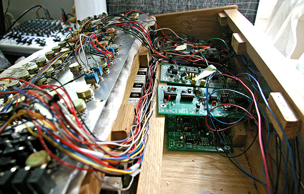 More boards installed and I'm beginning to get a sense of how much wiring I'm going to have to do.
 To keep all the wires in place...
 I used cable ties.
This made it a lot easier to keep track of all the wires but still, wiring up the whole things was definitely the most tedious part of the whole project.
In total there's roughly somewhere around 120-140 meters of cable inside of it.
I used cable ties.
This made it a lot easier to keep track of all the wires but still, wiring up the whole things was definitely the most tedious part of the whole project.
In total there's roughly somewhere around 120-140 meters of cable inside of it.
 Testing and calibrating pitch and mod wheels.
 Most pots and switches in place.
 Waveform selection switch and voltage and voltage divider soldered directly to the octave switch. Originally I built the octave switch unbuffered but that didn't work as intended of course. After adding a buffer to keep the cv summer from loading down the divider it works perfectly.
The octave switch covers 5 octaves and together with a 3 octave keyboard theis gives a range of 9 octaves.
 Finished at last.
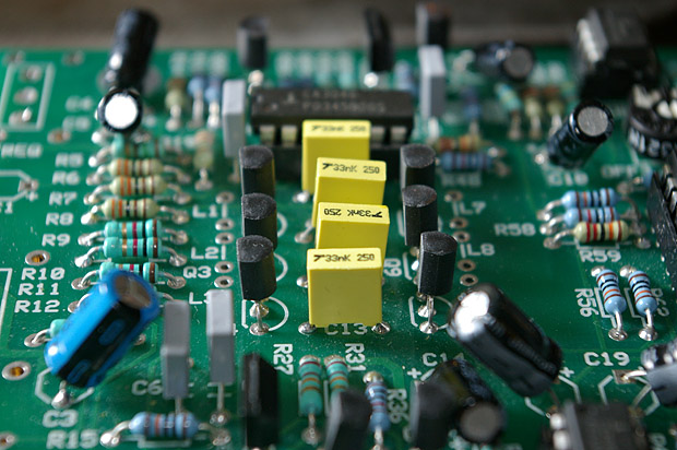
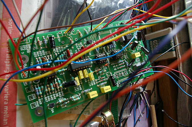
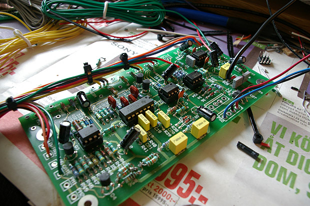
 Oscillator boards with Steiner filter to the right.
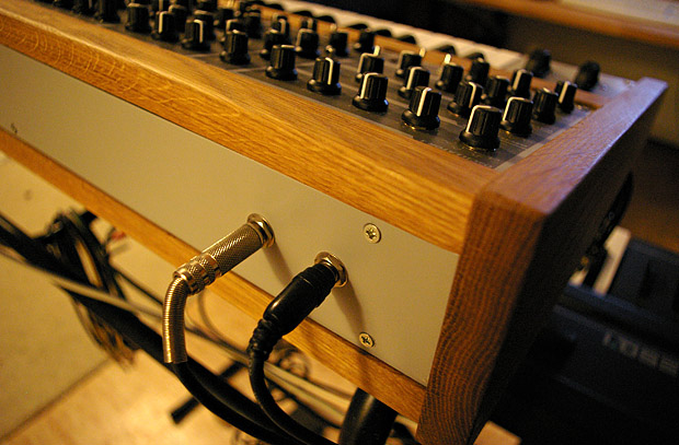 Finished, rear side.